First, here is a little history behind the meaning of the acronym,
JAMMA. Back in the dark ages of arcade video games (pre 1984),
game manufacturers operated in exclusive little domains where they designed game
components in a way that best served their own interests.Consequently, they each had their own proprietary circuit boards,
power supplies, and wiring harnesses. There
was essentially no interchangeability of components between one manufacturer's game
cabinet and a game cabinet made by someone else.While this worked well for the manufactures, it created massive startup and support costs for the Arcade operators. Around 1985,
the Japan Amusement Machinery Manufacturers Association (JAMMA) created some industry
standards, particularly for the design of game printed circuit boards (pcbs) and wiring harnesses,
the industry changed significantly.
The most important and influential of these new standards was
the pcb standard pinout. Any game pcb complying
with that pinout standard is what we now call a JAMMA board.
 The image to the left is of the parts side of a JAMMA
game board.
The image to the left is of the parts side of a JAMMA
game board.
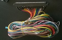 The wiring that connects the game's components - monitor, power
supply, control panel, speaker, etc. - to the pcb is called a JAMMA wiring harness.
The wiring that connects the game's components - monitor, power
supply, control panel, speaker, etc. - to the pcb is called a JAMMA wiring harness.
There are many JAMMA terms that you will come to hear and use
frequently - JAMMA board, JAMMA harness, JAMMA edge connector, JAMMA cabinet, and
so on.
At the root of their meaning is nothing more than the concept
of pcb interchangeability between cabinets of different manufacturers.
When you tire of a game, you can plug-and-play the JAMMA pcb
for your next favourite game. Plug-and-play
simply means to unplug the edge connector from one pcb, and plug it onto another
pcb.
Of course you need to be absolutely sure you have the plug
orientation correct, or you can blow the PCB by putting power on to connections
that weren’t meant to receive power.
And, it is the JAMMA standard pcb pinout (charted below) that
has made it all possible.
The following JAMMA pinout chart is basically a map of the JAMMA
wiring harness 56-pin edge connector. When
properly seated to the pcb, the connectors of the edge connector will align with
the pinout fingers of the pcb, and your game will play.

Understanding the JAMMA Pinout Chart:
Solder Side - The
bottom side of the pcb. The side where the
soldered connection parts are exposed to view.
Few, if any, parts are located on the solder side.
Parts (Component) Side -
The top side of the pcb. The side
where the electronic component parts are located. The parts side can be viewed in the pcb photo
above.
N/C - No connection.
Key Slot - A keyed slot which aligns with a leave-out in the
pinout section of the pcb.
This safety feature is provided to assure that the Power Section
seats at the correct end of the pinout section.
If the edge connector is reversed, and the Power Section is seated at the
opposite or incorrect end, irreparable damaged can occur to the pcb.
If the key has been removed from the edge connector, then mark
the connector as to the "Parts Side" to help assure correct seating.
Power Section - Pins A-F, 1-6
Video Section - Pins N, P, 13-15
Coin Section - Pins J, K, T, 8, 9, 16
Controller (Joystick) Section - Pins V-Y, 18-21
Pushbutton
Switch Section - Pins Z-b, 22-24 (for standard) and includes pins
c, d , 25, and 26 for Jamma+ (buttons 4 and 5) - many of the
chinese made multigame boards allow you to modify the harness to
use 27 and e for button 6
Ground (Common) Section - Pins f, 28 (incorrectly often
called Ground, correct term is Common)
A more detailed harness breakdown is available here